
Rigid-Flex PCB
When designing a rigid-flex printed circuit board, there are many considerations. The main challenge is how to balance flexibility and rigidity. Another important factor is to choose a manufacturing company that understands rigid-flex PCB assembly. This will ensure that your design meets all requirements and reduces the time to market.
To make a rigid-flex printed circuit board, copper foils are laminated to a polyimide or polyester-based film. The copper foils are available in two forms – electro-deposited and rolled. Both forms are subjected to surface treatment to improve longevity, enhance adhesion, augment bond strength, and protect against oxidation. The cladding process is followed by the application of an epoxy or urethane adhesive. The flex circuit is then cut and etched. This is followed by a plating process to form the layer-to-layer electrical connections. The etched and plated flex circuit is then laminated with the rigid pre-pregs or cores, with additional adhesive, heat, and pressure.
During this stage, the rigid-flex printed circuit board and rigid sections are laminated together with the addition of stiffeners where required. Stiffeners are used to prevent flex circuits from deforming under the stress of mechanical operation and they can also provide additional support for SMT components that are placed close to the flex section.
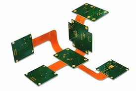
How is a Rigid-Flex PCB Manufactured?
The flex circuits and stiffeners are then routed with conventional mechanical routing tools. However, this is a difficult task because of the ductility of polyimide and the fact that routed edges are ragged. This can create mechanical stress concentrators and lead to flex-layer tearing. To avoid this, it is recommended to use thicker traces in the flex-section.
After the flex and rigid sections are assembled together, the hole locations are drilled and then plated with copper to the appropriate specifications. This step is crucial to the operation of the circuit and requires great care and attention.
Rigid-flex boards are designed to withstand high vibration conditions, making them ideal for applications in harsh environments. Vibration can cause mechanical stress on the traces and pads of a circuit board, resulting in failures that can affect the reliability and performance of the final product. To combat this, rigid-flex boards are manufactured with specialized materials that are designed to provide better resistance to dynamic flexing and increased structural integrity.
A rigid-flex board must also be able to withstand the high levels of electromagnetic interference (EMI) generated by electronic devices and the transmission of signals between them. To reduce EMI, the circuitry is often shielded with an aluminum or copper metallization.
Once the flex and rigid sections are assembled, they must undergo stringent electrical testing to verify that they meet all design specifications. This can include a grid and flying probe test. The flex section can also be tested for continuity, isolation, and circuit performance. Once all tests are complete, the rigid-flex PCB can be packaged and delivered to the customer.
