
interface a circuit board with a microcontroller
Interfacing a circuit board with a microcontroller is a fundamental task in electronics design, enabling the microcontroller to control various functions and processes within a system. This interaction is crucial in applications ranging from simple devices like LED controllers to complex systems such as robotics and automation equipment. Understanding the steps and considerations involved in this process can help ensure successful communication between the circuit board and the microcontroller.
A microcontroller is a compact integrated circuit designed to govern a specific operation in an embedded system. It typically contains a processor core, memory, and programmable input/output peripherals. The circuit board, on the other hand, is a substrate that houses electronic components, including resistors, capacitors, sensors, and communication interfaces. To interface these two components effectively, it is essential to understand the functionality of the microcontroller and the components on the circuit board.
The first step in interfacing a circuit board with a microcontroller is selecting the appropriate microcontroller for the application. Factors to consider include the number of I/O pins required, processing speed, available memory, and compatibility with peripheral devices. Microcontrollers are available in various architectures, such as ARM, PIC, and AVR, each with unique features and benefits. For instance, an ARM microcontroller may be chosen for applications requiring high processing power, while a simpler AVR microcontroller may suffice for basic tasks.
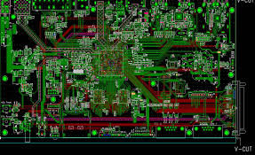
How do you interface a circuit board with a microcontroller?
Once the microcontroller is selected, the next step is to establish the physical connections between the microcontroller and the circuit board. This involves wiring the I/O pins of the microcontroller to the corresponding components on the circuit board. It is essential to ensure that the voltage levels of the microcontroller and the components are compatible. For example, if the microcontroller operates at 3.3V, connecting it directly to a 5V component could damage the microcontroller. In such cases, level shifters or voltage dividers may be required to ensure proper voltage compatibility.
After establishing the physical connections, the microcontroller needs to be programmed to interact with the circuit board. This programming typically involves writing code in a suitable language, such as C or C++, using an Integrated Development Environment (IDE) specific to the microcontroller’s architecture. The code will define how the microcontroller reads input from sensors or switches, processes that data, and sends output signals to control actuators or other components.
During programming, it is crucial to implement appropriate timing and control logic, especially in real-time applications. Interrupts may be utilized to handle events that require immediate attention, ensuring that the microcontroller can respond effectively to changes in the environment.
Once the connections are made and the microcontroller is programmed, the system must be tested to ensure that it operates as intended. This involves checking the functionality of each component, verifying that the microcontroller correctly processes inputs and produces the desired outputs. Debugging tools, such as oscilloscopes or logic analyzers, can be invaluable during this phase, allowing engineers to monitor signals and identify issues within the system.
It’s essential to conduct thorough testing under various operating conditions to ensure reliability. This testing phase may also involve modifying the code to optimize performance or fix any identified bugs.
